
Garage Door Monitor Project
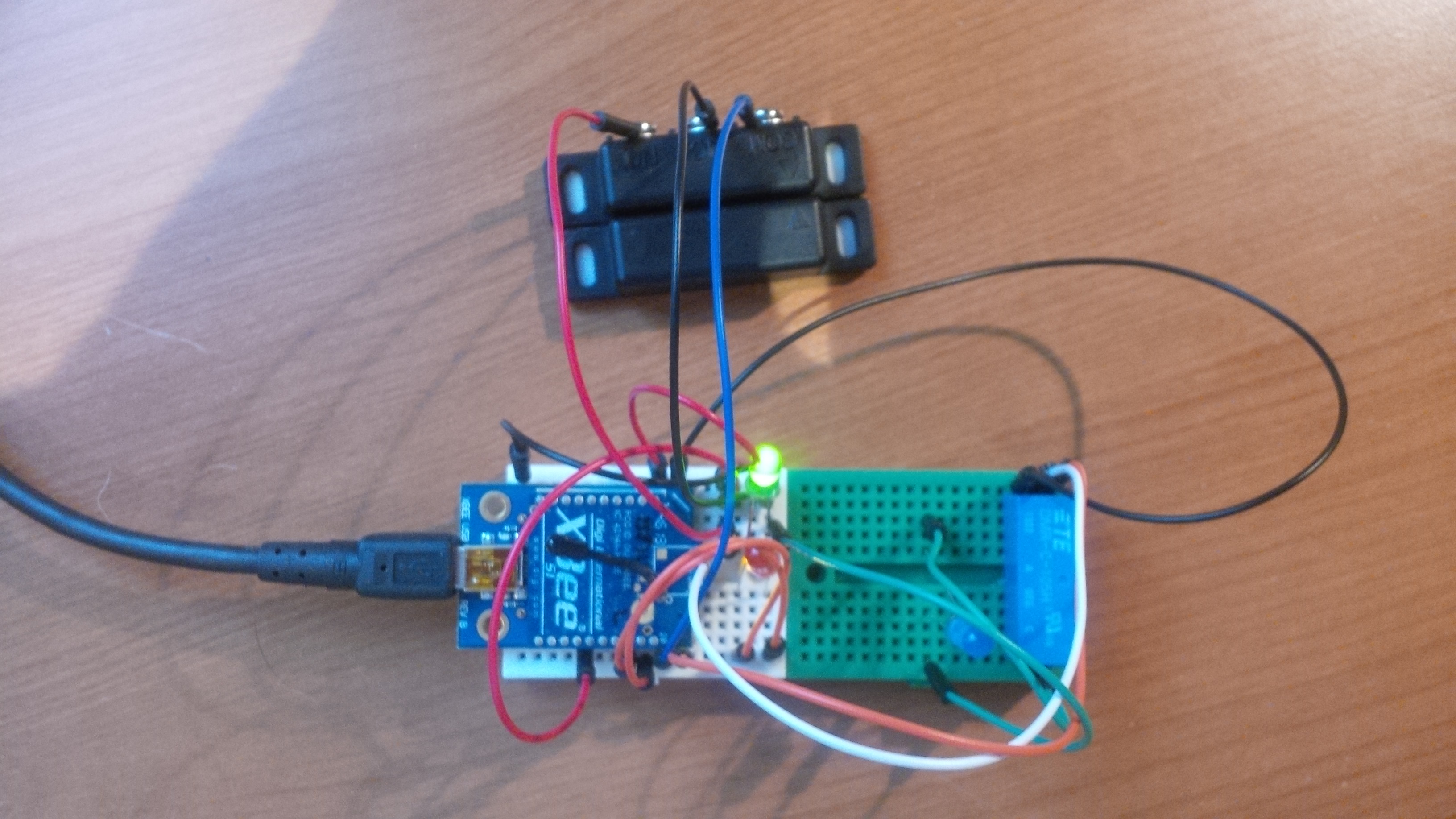
Prototype on my desk – black thing at the top is the reed switch that will mount to the door (green led is lit to show door is closed) – blue thing at the far right of the breadboard is a 3v relay – when it closes it will close the circuit on the garage door push button)
Background: While surfing around trying to educate myself on how to use the XBEE gadgets to enable the solar monitor project I happened upon some posts about people using them to monitor the status of their garage doors. This struck me as a very practical application that could actually benefit us and leverage the work that I had already done. On occasion we have gotten up (typically on the weekend in the summer) to find that we left our garage door open all night long. Fortunately, this has never been an issue but it’s probably smarter if we don’t do it. There was some minor crime in our neighborhood last winter when someone went around at night breaking into all the cars parked in driveways – nothing serious but probably better if we don’t tempt anyone by leaving our garage door wide open!
So, with that thought, a new project was born and it really only required a few additional parts. Here’s what I used:
Parts List:
| ITEM | DESCRIPTION | COST | PIC |
| Total cost = $64 | |||
| Raspberry Pi | Credit-card sized linux server that runs Apache and MySQL and hosts the various php and python code files – I already had this but it sells for $35 | $0 |  |
| XBEE Radio – Receiver | This connects to the Raspberry Pi sever so it can receive data from the remote unit (already had this in place from the solar monitor project) | $0 |  |
| XBEE Radio – Transmitter | (Same as the receiver) – I needed a new one for this project as I couldn’t leverage the one from the solar monitor project | $29 | |
| XBEE Shield | This isn’t necessarily required but made life a lot easier (saves soldering and handles the power mgmt on the board) | $19 |  |
| Reed Switch | This gets mounted on the garage door and let’s the system determine the open/closed state of the door | $5 |  |
| 3v Relay | This lets me trip the existing garage door opener button next to the door in the garage by sending a command to the remote XBEE | $4 |  |
| Breadboard | I initially got this just for easy proto-typing but this cool package of 6 little ones was a great find and 2 of them wound up in the final build! | $7 |  |
| 5v USB Power Supply Cord | I seem to always have a handful of these lying around at any one time from old phones, toys, etc | $0 |  |
| Wire | I just used some old telephone wire I had in the shop | $0 |  |
| Various jumper wires, leds, etc | I had these from the kit I bought and used in the solar monitor project | $0 | 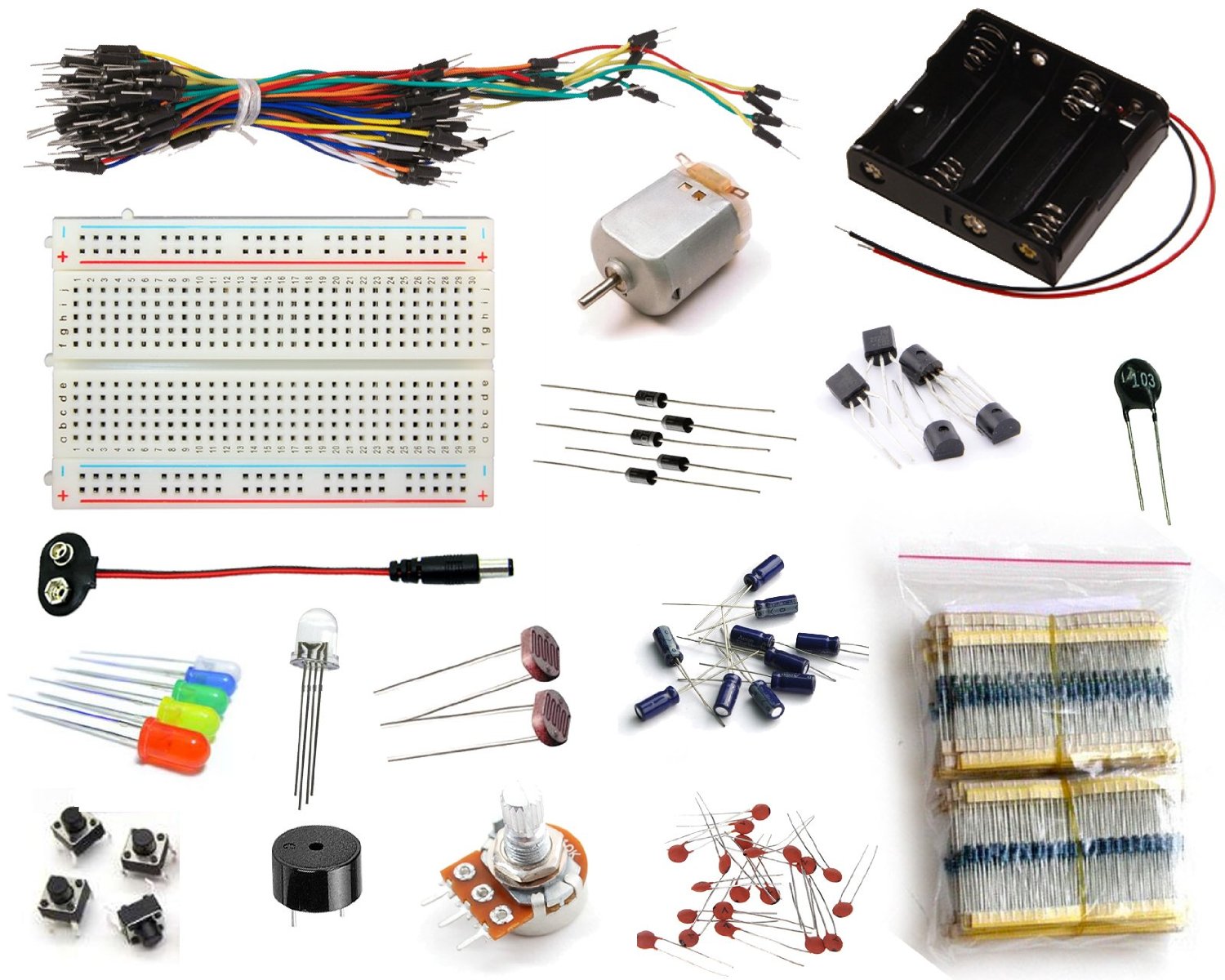 |
| Enclosure | I used a blueberry container from the grocery store that was sitting in the recycling bin! | $0 |  |
Code: Once I had all the parts it was a matter of cobbling the code together to make it all work. I had the XBEE stuff all figured out already from the earlier work on the Solar Monitor so it wasn’t hard to tweak that. Putting it all together consisted of the following pieces of code:
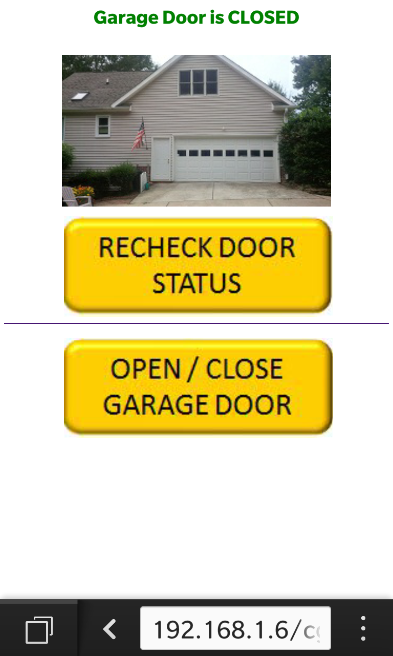
- Read the state of the reed switch to know whether the door is open or closed – essentially just monitoring one of the digital input pins on the XBEE to see if the switch is open (high) or closed (low) – also spits out some html so you can interface to this from a browser (only accessible on the local home wifi network):
12345678910111213141516171819202122232425262728293031323334353637383940414243444546474849505152535455#!/usr/bin/pythonfrom xbee import XBeeimport serialimport timeimport cgiprint "Content-type: text/html\n\n"print "<html><head><title>Garage Door PI</title>"print "<style>img.responsive {width : 70%; /* or max-width : 100% */height: auto;}"print "H2 {font-size: 250%;}"print "</style>"print "</head><body>"SERIALPORT = "/dev/ttyUSB0"BAUDRATE = 9600ser = serial.Serial(SERIALPORT, BAUDRATE)ser.open()xbee = XBee(ser)remote_addr="\x00\x13\xa2\x00\x40\xb3\x65\x78" # XBEE on BLUE Shield (BAD ADC-0)xbee.remote_at(dest_addr_long=remote_addr,command='IS', frame_id='A')response = xbee.wait_read_frame()#print response (used for debugging...)samples = response['parameter']# XBEE pin dio5 checks the garage door reed switch state...for each in samples:dio = each['dio-5']if not dio:print "<center><H2><font color=green>Garage Door is CLOSED</font></H2><BR><img src=\"http://192.168.1.4/images/DOOR_CLOSED.jpg\" class=\"responsive\"><BR>"xbee.remote_at(dest_addr_long=remote_addr,command='D2',parameter='\x04')xbee.remote_at(dest_addr_long=remote_addr,command='D3',parameter='\x05')else:print "<center><H2><font color=red>Garage Door is OPEN!</font></H2><img src=\"http://192.168.1.4/images/DOOR_OPEN.jpg\" class=\"responsive\"><BR>"xbee.remote_at(dest_addr_long=remote_addr,command='D3',parameter='\x04')xbee.remote_at(dest_addr_long=remote_addr,command='D2',parameter='\x05')# wait 1 secondtime.sleep(1)ser.close()print "<BR>   <a href=\"http://192.168.1.4/cgi-bin/garage_web.py\"><img src=\"http://192.168.1.4/images/RECHECK_BUTTON.jpg\" class=\"responsive\"><BR><HR></a>"print "<BR>   <a href=\"http://192.168.1.4/cgi-bin/garage_remote.py\"><img src=\"http://192.168.1.4/images/OPEN_CLOSE_BUTTON.jpg\" class=\"responsive\"></a>"print "</body></html>"

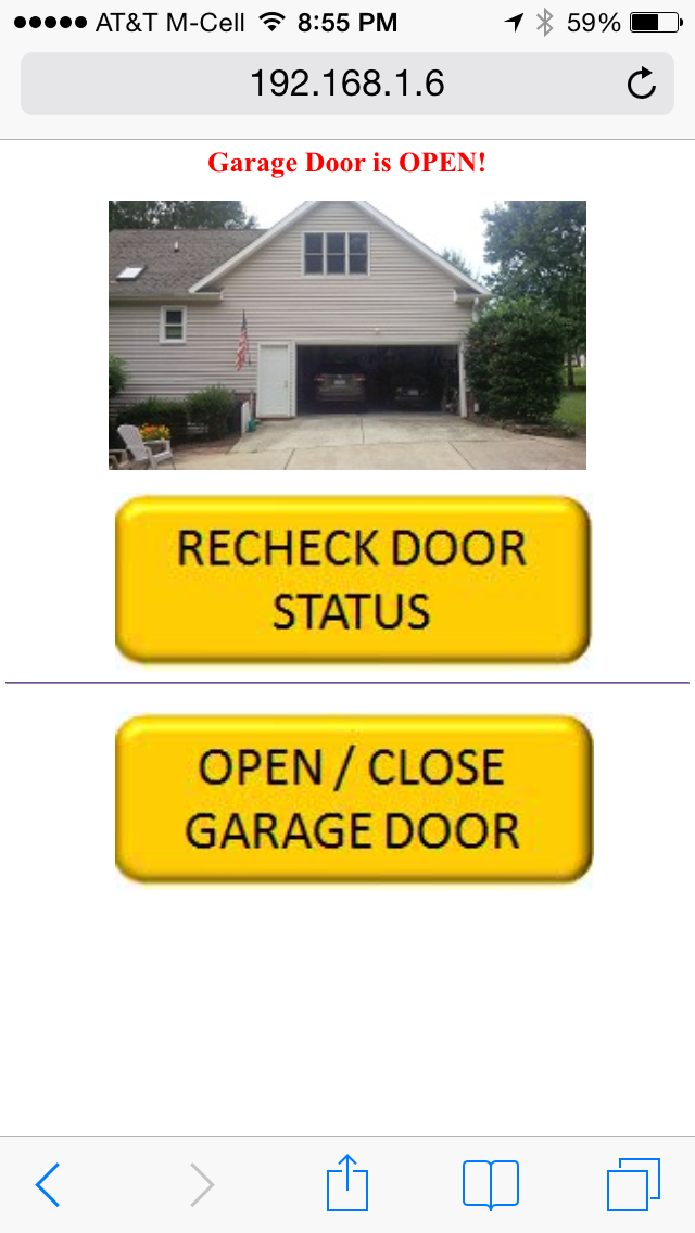
Web page on Donna’s iPhone showing that the door is open…
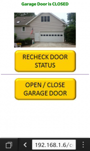
Web page on Jeff’s BlackBerry shows the door is closed…
- Send a command to “push” the button on the garage door opener to open or close the door – basically just change the XBEE digital io pin #0 to high for 1 second to close the circuit on the garage door opener push button via the 3v relay. We do the same with the XBEE dio pin #4 which has a blue led connected to it just for a visual indication.
12345678910111213141516171819202122232425262728293031#!/usr/bin/pythonfrom xbee import XBeeimport serialimport timeprint "Content-type: text/html\n\n"print "<html><head><title>Garage Door PI</title>"SERIALPORT = "/dev/ttyUSB0"BAUDRATE = 9600ser = serial.Serial(SERIALPORT, BAUDRATE)ser.open()xbee = XBee(ser)remote_addr="\x00\x13\xa2\x00\x40\xb3\x65\x78" # XBEE on BLUE Shield (BAD ADC-0)xbee.remote_at(dest_addr_long=remote_addr,command='D0',parameter='\x05')xbee.remote_at(dest_addr_long=remote_addr,command='D4',parameter='\x05')time.sleep(1)xbee.remote_at(dest_addr_long=remote_addr,command='D0',parameter='\x04')xbee.remote_at(dest_addr_long=remote_addr,command='D4',parameter='\x04')ser.close()time.sleep(8) # Wait 8 seconds for garage door to complete the open or close cycle...print "<META http-equiv=\"refresh\" content=\"1;URL=http://192.168.1.4/cgi-bin/garage_web.py\"></head><body></body>" - A cron job running on the Raspberry Pi server at 8:30 pm launches a python program which checks the garage door status (ie check the status of XBEE dio pin #5 which is reading the state of the reed switch – if the pin is high the door is opened, low it is closed) and sends us a text message if the door is still open (with a link to close it if it is!)
12345678910111213141516171819202122232425262728293031323334353637383940#!/usr/bin/python# This will run via cron job at 9pm and check whether the door is openimport subprocessfrom xbee import XBeeimport serialSERIALPORT = "/dev/ttyUSB0"BAUDRATE = 9600ser = serial.Serial(SERIALPORT, BAUDRATE)ser.open()xbee = XBee(ser)# Pull status of door...remote_addr="\x00\x13\xa2\x00\x40\xb3\x65\x78" # XBEE on BLUE Shield (BAD ADC-0)xbee.remote_at(dest_addr_long=remote_addr,command='IS', frame_id='A')response = xbee.wait_read_frame()samples = response['parameter']for each in samples:dio1 = each['dio-5']# If door is open then send text message...if dio1:# Launch the PHP code that can send an SMS via GoogleVoice (can't do this with python...cmd = "/usr/bin/php /var/www/gvoice.php"p = subprocess.Popen(cmd, stdout=subprocess.PIPE, stderr=subprocess.PIPE, shell=True)print "Garage door open - text message sent..."else:print "Garage door is closed - no action needed..."ser.close()
…this actually calls a php file to send the text message through Google Voice as I could not get this to work natively in python and gave up after much frustration:
123456789101112<!--?php require 'class.googlevoice.php'; $phone_num = '919xxxxxxx'; //Jeff BBerry Phone $phone_num2 = '678xxxxxxx'; //Donna iPhone $msg = 'The garage door is open! Click here to close -----------> http://192.168.1.60/cgi-bin/garage_remote.py';$gm_username = 'xxxxx';$gm_password = 'yyyyy';$gv = new GoogleVoice($gm_username, $gm_password);$gv->sms($phone_num, $msg);$gv->sms($phone_num2, $msg);echo $gv->status;?>
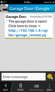
Text Message telling us that we forgot to close the garage door!

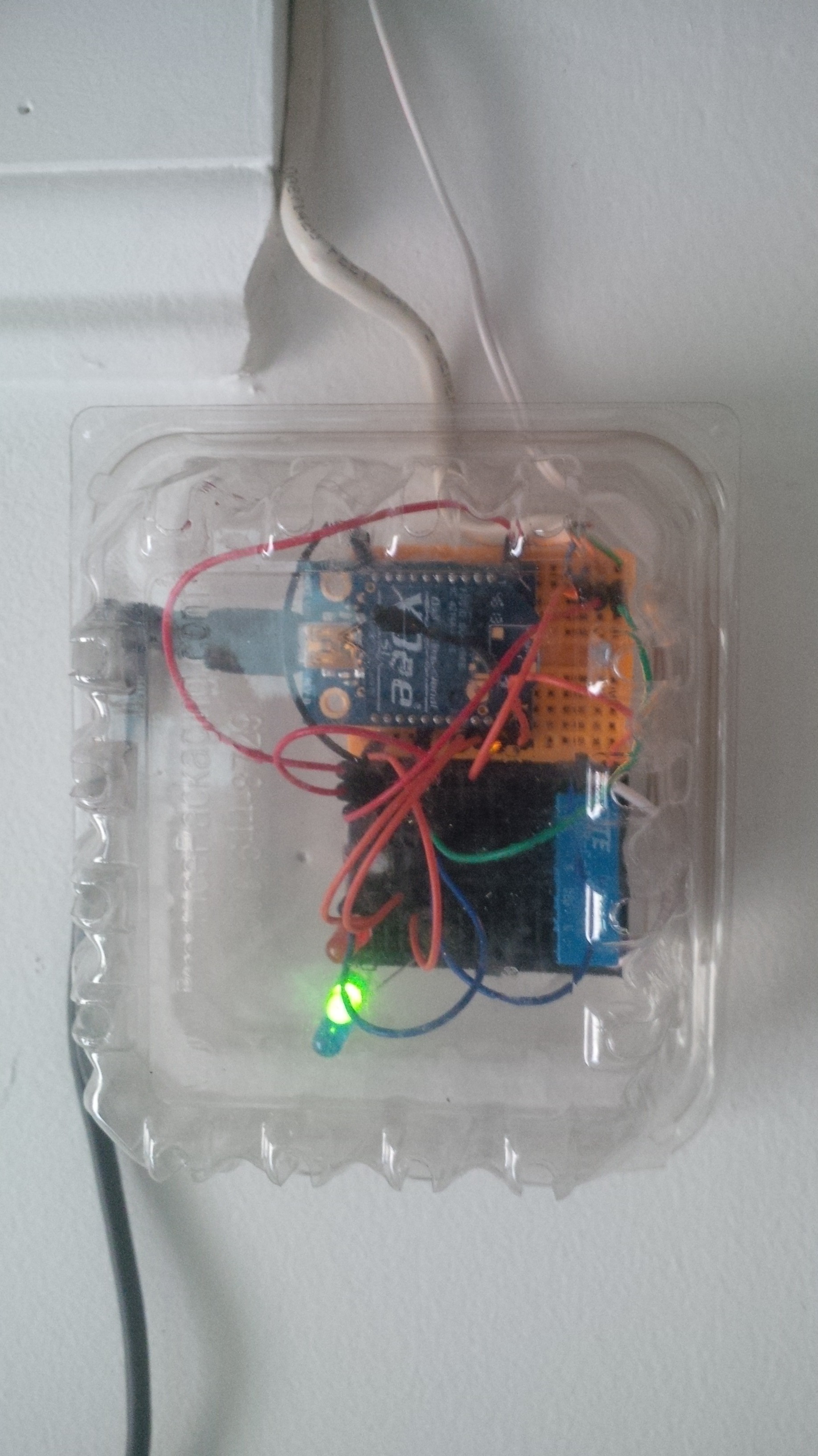
With the blueberry plastic box closed up (the air holes in the box are nice for keeping things from getting too hot in the summer time)
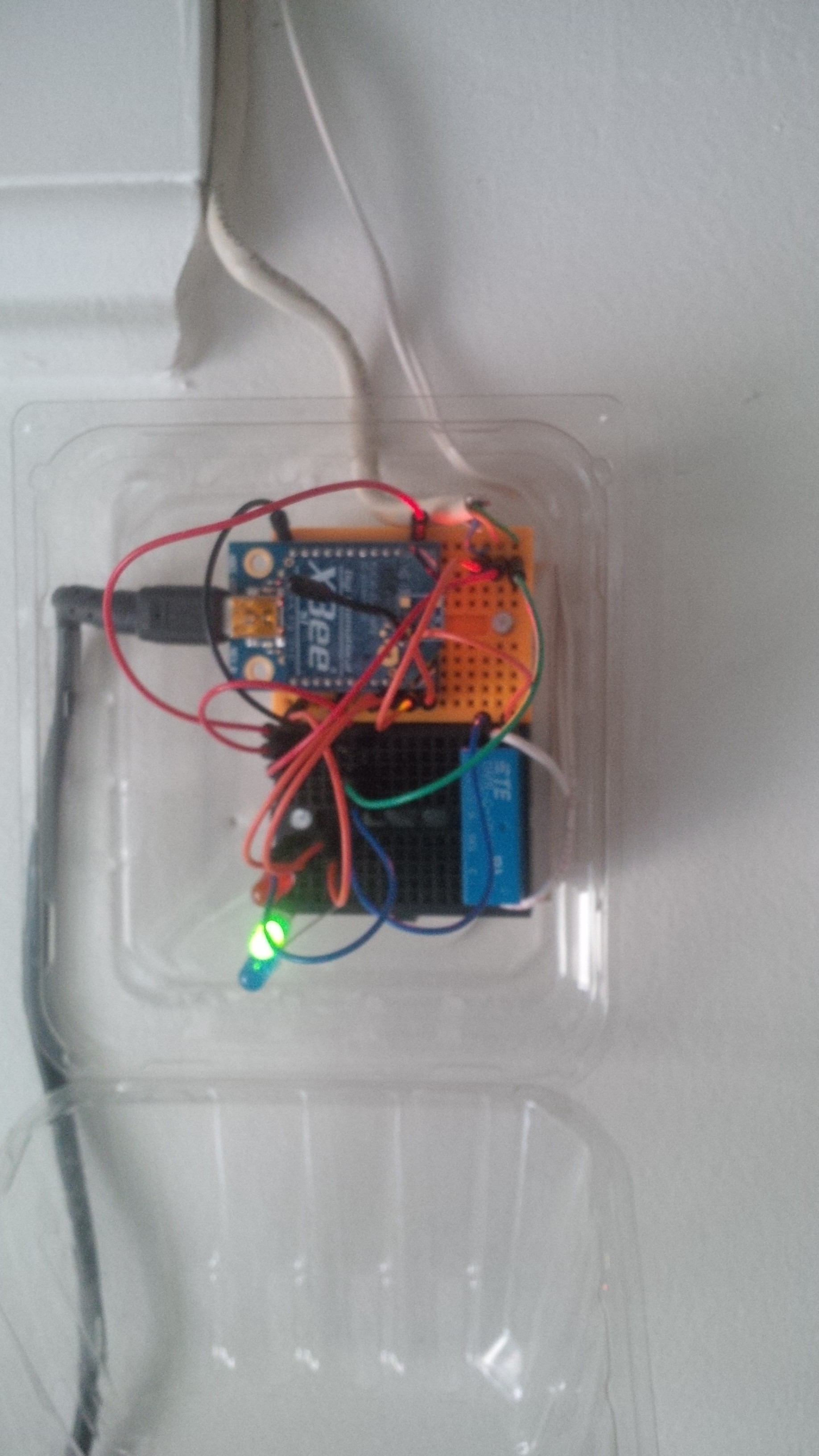
Final installation – mounted to the inside garage wall. Black wire on the side is power – white wires at the top route to the reed switch and push-button opener
Installation: Mounting it in the garage was fairly easy using some old telephone wire that was lying around in my shop. Here’s the final installation (note the high-tech enclosure – aka a used plastic blueberry container that was about to go out in the recycling bin!) It’s up in a corner of the garage – conveniently close to a power outlet and short wire runs from the reed switch on the actual garage door and the push button opener right next to the inside entry door.
Key Challenges:
- I initially bought a 5v relay to close the door opener switch – not sure what I was thinking but the XBEE maxes out at 3V so I spent some time scratching my head and eventually bought the right one.
- The XBEE has a VREF pin that winds up being very important – it essentially tells the chip what the incoming voltage level is and it’s important in any calculations you do on the readings from the analog pins as well as measurements you might be making with a multimeter. I didn’t fully understand this at first and neglected to supply it with the proper voltage.
- When I first installed the reed switch on the garage door it got in the way of the cable as the door was moving up and down. It didn’t cause any problems but would make a loud “snap” when the cable moved around the switch. Donna nearly jumped out of her skin when she first hit the button after I installed it. Fortunately it was a quick easy fix.
- In normal fashion, after everything was prototyped and working like a champ, I then pulled my hair out for 2-3 days after cleaning it up and installing it in it’s final production spot. The pin checking the status of the reed switch would not always read correctly. I rebuilt everything a few times, cussed myself endlessly and only finally got smart and used good troubleshooting technique to break it down into lots of little parts. One of the jumper wires I put into the breadboard had somehow gone flaky – arrrgh!
Next steps:
- So far it is running like a champ without issue for a few weeks. I’m not sure how stable everything will stay but if there’s any flakiness I may need to automate a reboot/reset once a month or so.
- I might be too lazy for this but it could probably stand to move onto a pcb prototype board with some good soldered connections rather than the breadboard + jumper wires that it’s built with now.
- There are red/green LED’s that visually indicate whether the door is open or closed but they only update when the program to check the door status is run. So, if the door is opened or closed normally from one of the remotes or from the wall switch then the LED’s are not correctly lit. This is very minor and the best solution might be to just eliminate the LED’s as they’re really not needed but maybe I can come up with something more creative.
- I might change out the pics on the web page that show the door either opened or closed so they feature 5-year old Katie standing in front of the door (since we always smile when we see her pic!)
Acknowledgements: A couple of good web links helped me as I was tinkering with this:
http://www.robtennyson.us/post/zigbee-xbee-garage-door-opener
http://karlduino.wordpress.com/2012/09/23/arduinoxbee-garage-door-indicator/
http://www.adafruit.com/blog/2009/04/21/using-xbees-to-control-relays/